RoboticsFirst semester · November 2024
Maze Runner & Ball Shooter
Two robots for a first-semester university competition
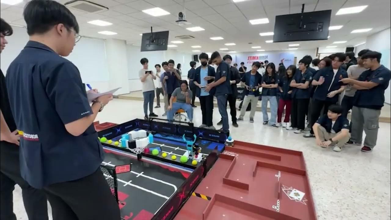
System Overview
For a first-semester competition in November 2024, our three-person Circuit Breakers team built two robots: one to carry a ball through a maze autonomously, and another to shoot balls under gamepad control.
The maze robot uses three ultrasonic sensors and Arduino C++; the Makeblock shooter uses Python to control its drive, shooter motor, and ball-handling servos.
How it actually works
Two robots, two control loops
Place the maze robot in a junction to see its real sensor rules decide the wheel speeds, then drive the shooter's real gamepad code.
Things to try
- In Turn toward openings, pick T-junction and Dead end.
- In Mix the joystick, push the stick to a corner and see the ±1 clamp.
- In Shoot and release, press R2.
Built from the project's own code and documents.from code: A constant or rule copied from the project's repositoryfrom report: A value from the project's report or presentationsimulated: Computed in your browser by running the project's logic
How it works
Build two robots with different control requirements.
- 1
Read maze distances
NewPing reads the front, left, and right ultrasonic sensors to supply distances for the Arduino navigation loop.
- 2
Adjust maze wheel speeds
Correct the difference between side distances, turn toward detected openings, and stop when both sides and the front are too close.
- 3
Drive the shooter manually
Mix joystick inputs into left and right wheel speeds, and use gamepad buttons to start or stop the shooter motor.
- 4
Position and release the ball
Move the grabber and claw servos through bounded button inputs, or trigger the timed grabber-position and claw-release sequence.
Project Demo
The project's own demonstration footage.
Engineering features
Maze navigation: three ultrasonic sensors measure the front and side walls so the Arduino can steer toward openings while carrying a ball.
Differential motor control: C++ and NewPing adjust left and right wheel speeds through an L298N driver, constrain PWM to 0–255, and stop when both sides are under 15 cm and the front is under 5 cm.
Manual shooting: Python on Makeblock mBot2 mixes joystick inputs for differential driving, with gamepad buttons starting and stopping the shooter motor.
Ball handling: separate grabber and claw servos use bounded 0–180° controls and a timed release sequence, supported by custom mechanical CAD assemblies.
Inside the build
The control logic, integration and design decisions, one note at a time.
01Reactive differential maze control
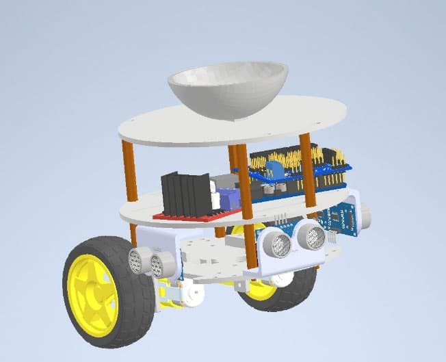
The C++ program stores motors and ultrasonic sensors in arrays and computes a correction from the left-right distance difference. Side-opening rules add a turning boost; the blocked-path condition stops both motors. PWM commands are constrained to 0-255 and applied through the L298N driver in a repeated sensor-feedback loop.
02Gamepad mixing and bounded ball handling
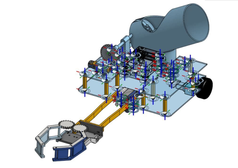
The Python program sums and subtracts normalized joystick axes to produce differential drive commands. Separate buttons operate the shooter motor and increment the two servo angles within 0-180 degrees. The release input sets the grabber position, waits briefly, and then opens the claw; the operator initiates this sequence.
03Mechanical assemblies documented in CAD
The maze assembly places the ball holder above the controller, driver, wheels, and three ultrasonic sensors. The manual robot's CAD documents the shooter barrel, gear track, motor mounts, connecting arms, and claw assembly. These illustrations show component placement and mechanisms without substituting CAD for physical-build evidence.
Build artifacts
Figures taken from the project's own report or presentation.
Evidence & limitations
What the project documents show, and where each claim comes from.
Code, flowcharts, and assembly illustrations
The 27-page Computer Programming for RAI report contains both programs, explanations, flowcharts, component CAD, and complete assemblies. Its cover names the three Circuit Breakers members and dates submission to 11 November 2024. A competition demonstration is linked in the supplied portfolio.
- Computer Programming for RAI competition report
PDF page 1: team and date; 2-11: maze code and CAD; 12-15: manual shooter control; 15-27: shooter CAD. Individual contribution confirmed by Lucky.
- Competition demonstration
Linked from the supplied portfolio.
Project Resources
The original documents behind this case study.
Hiring for robotics or embedded work?
I'm looking for internships. The résumé has the short version.