
System Overview
Two ESP32 units connect environmental sensing to a portable LCD and PM2.5 indicator LEDs.
The sensor measures particulate matter, CO2, temperature, and humidity using rechargeable power with solar charging. The presentation records lab comparisons and power tests, alongside unstable readings, limited wireless range, and weather-constrained solar evaluation.
Tech Stack
Solar Powered
Sustainable operation with battery backup
Multi-Sensor
PM2.5, CO2, temperature, humidity integration
Real-Time Monitoring
Live wireless data transmission
Project Demo
Engineering Features
Developed a solar-powered air quality monitoring system with wireless data transmission and real-time environmental sensing.
Integrated PM2.5, CO2, temperature, and humidity sensors into a single monitoring device and transmitted readings to a receiver unit, with optional laptop monitoring.
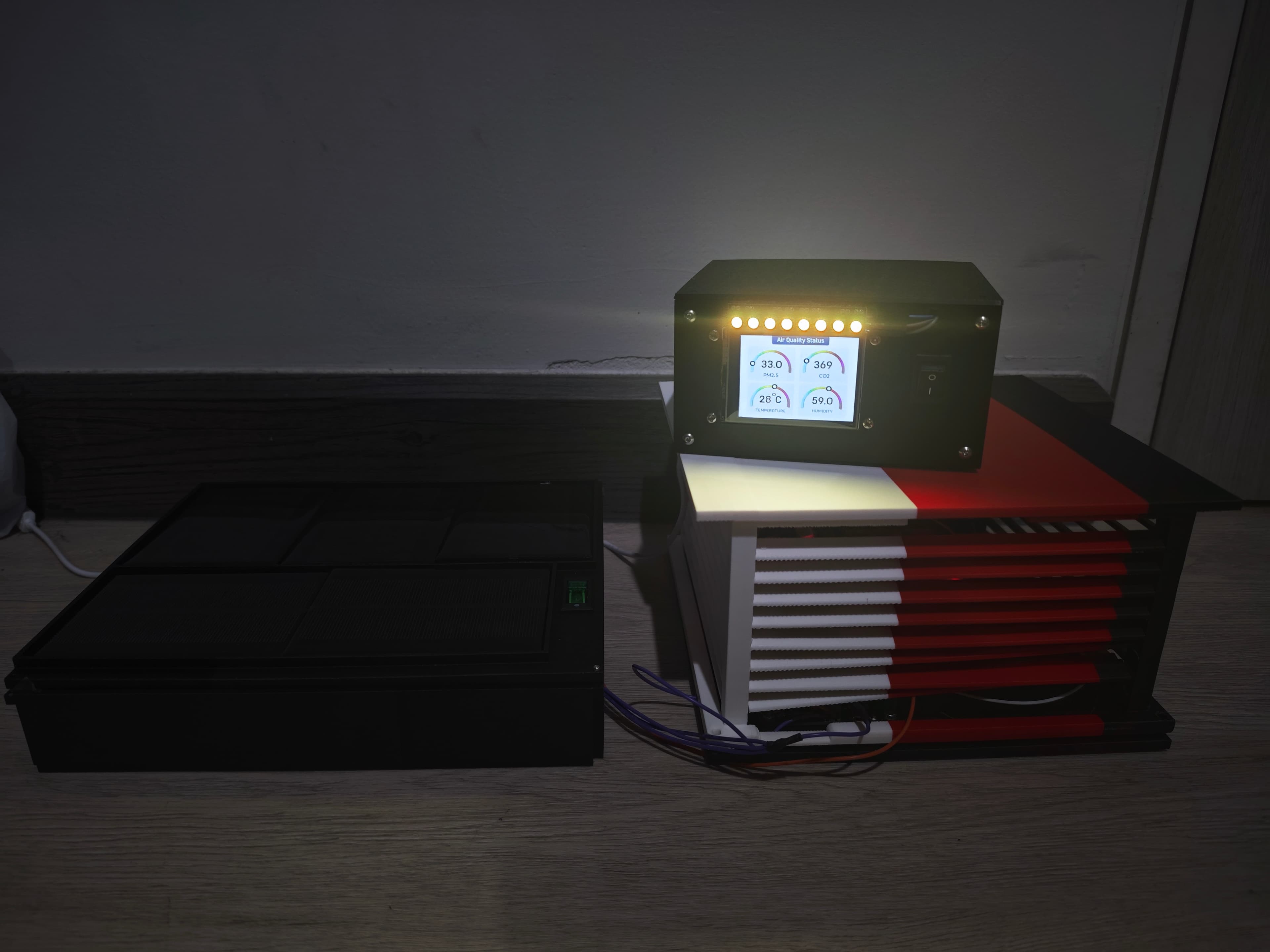
Built a portable receiver unit with a display and LED indicators for real-time air-quality visualization.
Conducted controlled indoor and outdoor tests to validate measurement accuracy and system reliability.
How it works
Sample environmental conditions
The sensor ESP32 collects readings from the particulate, CO2, temperature, and humidity sensors housed in the ventilated sensing unit.
Transmit readings wirelessly
Send the sensor data to the receiver ESP32, with the system also supporting viewing readings on a connected computer.
Display local air-quality information
Present readings on the receiver's LCD and control its indicator LEDs according to the measured PM2.5 level.
Build artifacts
Inside the build
Open a technical note to explore the control logic, integration, and design choices.
Separate sensing and display hardware
The system uses two ESP32 boards, a PMS5003 particulate sensor, an MG811 CO2 sensor, and a DHT22 temperature/humidity sensor. The receiver combines an LCD with an LED strip, allowing the sensing hardware and the user-facing display to occupy different locations.
Solar charging evaluated alongside load
Parallel solar panels feed the sensor charging system, and a rechargeable battery supplies the electronics through power conversion hardware. The presentation distinguishes component-based power calculations from measured charging and discharge tables. Solar output is shown with and without load, and cloudy-weather testing constrains the charging evidence.
Housing for airflow and monitoring
The sensor enclosure uses louvers for ventilation and a roof overhang intended to reduce direct rain entry. A separate solar box houses the charging arrangement. The receiver enclosure provides access to the screen and indicator lights, keeping the sensing, charging, and monitoring functions in distinct physical units.
Evidence & limitations
Lab comparisons and campus measurements
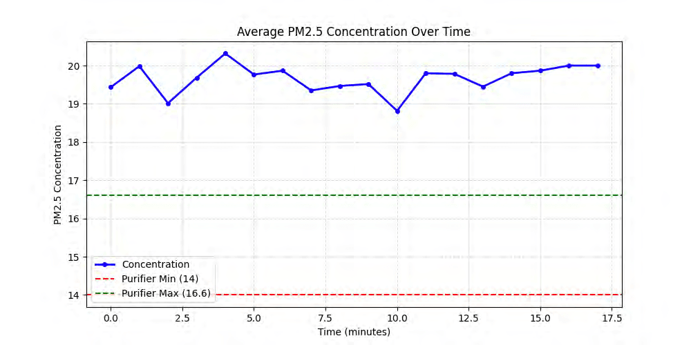
The presentation plots PM2.5 and CO2 readings in the HM lab and at campus locations. The PM2.5 lab comparison shows a positive offset from the purifier's readings; outdoor plots were taken at different times of day, so they do not establish a simultaneous location comparison.
Power and communication results
Charging and discharge tables document USB charging, solar charging, and battery operation. The conclusion reports data transfer between two ESP32 boards and a PC, plus display and LED operation, while acknowledging transmission-range and solar-testing problems.
- Air monitor project presentation
PDF pages 6-18: objectives, design, and power calculations; 20-29: tests; 30-31, 34: limitations and conclusion.
- Airlink source repository
- Project demonstration
Linked in the presentation and supplied portfolio.
CAD & Mechanical Models
Loading 3D preview…
Loading 3D preview…
Loading 3D preview…
Want to see more work?
I have more projects across robotics, embedded systems, and software engineering.
View All Projects