Embedded systemsDecember 2024 - April 2025
BLDC Motor FOC Control
Advanced Motor Control with STM32 and Field-Oriented Control
System Overview
This STM32 controller receives PC speed commands over Modbus RS485 and drives a BLDC motor with Field-Oriented Control.
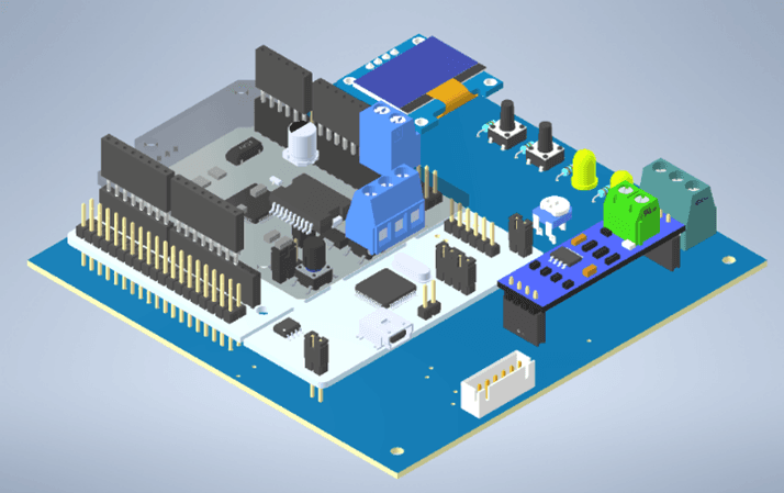
The published firmware runs the open-loop mode, with the report's closed-loop velocity controller left commented out; an SPI encoder reports angle and speed, and an OLED displays motor state. Interrupt-based communication and timer-driven control are integrated with a stop input, manually etched PCB, and custom printed enclosure.
How it actually works
Inside the Modbus BLDC controller
Follow one speed command through the published STM32 firmware: the Modbus frame, the 1-per-100 ms ramp, the 2.5 kHz timer tick, sine PWM, the encoder and the OLED.
Things to try
- Move the slider, press Send frame and watch only bytes 4 and 5 change.
- Open 2 Ramp and E-stop and press E-stop during a ramp.
- Compare the duty cycles in 4 Sine PWM with the OLED in 6 OLED.
Built from the project's own code and documents.from code: A constant or rule copied from the project's repositoryfrom report: A value from the project's report or presentationsimulated: Computed in your browser by running the project's logic
How it works
Connect PC commands to motor feedback and local control.
- 1
Receive a speed command
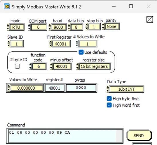
The MAX485 passes PC Modbus data to a UART receive buffer, and the callback extracts the requested speed from two data bytes.
- 2
Adjust the setpoint
The firmware increases or decreases the speed setpoint in steps toward the target, subject to the emergency-stop state.
- 3
Run the motor feedback loop
A timer callback measures elapsed time and calls the FOC and motor-control functions using encoder feedback and the current setpoint.
- 4
Expose motor state
Show measured angle, speed, and target speed on the OLED, or display the emergency-stop state when the stop input is activated.
Project Demo
The project's own demonstration footage.
Engineering features
Developed a BLDC motor control system using the Modbus protocol over RS485, with an STM32 microcontroller handling real-time communication and speed control.
Implemented Field-Oriented Control on a 2.5 kHz timer interrupt with sine PWM, an SPI magnetic encoder and interrupt-driven Modbus processing; a closed-loop PI velocity mode is documented in the report.
Designed and fabricated a custom PCB to house all the components into a single board.
Inside the build
The control logic, integration and design decisions, one note at a time.
01Interrupt-based RS485 direction switching
UART reception uses the STM32 HAL receive-to-idle interrupt interface. The receive callback switches the MAX485 into transmit mode and echoes the received frame; the transmit-complete callback restores receive mode. The target-speed value is assembled from the high and low bytes in the received buffer.
02Timed FOC with encoder feedback
The firmware initializes an AS5048A SPI encoder and the motor driver in open-loop mode with 7 pole pairs; the report lists a closed-loop velocity controller (P 5, I 30) that the published code leaves commented out. Timer 4 triggers control updates at 2.5 kHz, while Timer 1 supplies elapsed time. The callback invokes loop_foc and bldc_move, with encoder-derived angle and velocity also available to the display.
03Fabricated board and accessible enclosure
The team transferred a printed PCB layout to copper, corrected traces manually, and chemically etched the board. The enclosure divides component mounting and wiring into a base and top holder, with openings for the motor, front-facing OLED, and stop button so the operator can access controls without opening the case.
Build artifacts
Figures taken from the project's own report or presentation.
Evidence & limitations
What the project documents show, and where each claim comes from.
Reported integrated motor operation
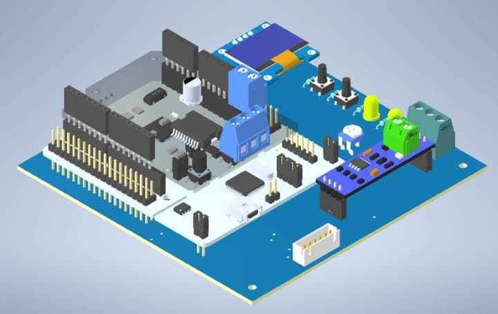
The report includes the board design, schematic, firmware listing, communication and speed-control diagrams, and a result-video reference. Its results section reports PC-commanded motor speed control, live OLED feedback, and operation of the stop button; it does not provide numerical speed-tracking or stop-latency measurements.
- BLDC controller project report
PDF pages 2-4: hardware and PCB fabrication; 5-15: firmware and control; 16, 18: results and conclusion.
- Motorpilot source repository
- Project demonstration
Linked from the supplied portfolio.
CAD & mechanical models
Drag to rotate each part; pinch, or hold Ctrl or ⌘ and scroll, to zoom. Models load as you reach them.
BLDC Motor
STLLoading 3D preview…
Housing Top
STLLoading 3D preview…
Housing Bottom
STLLoading 3D preview…
PCB
STLLoading 3D preview…
Project Resources
The original documents behind this case study.
Hiring for robotics or embedded work?
I'm looking for internships. The résumé has the short version.